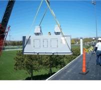
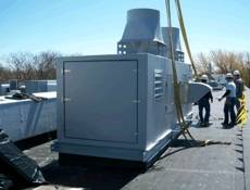
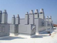
Fan SKYPLUME G2 – GIF
Entrainment stacks need to work in the outdoor environment in which they are installed. As crosswinds accelerate, it is important for public safety that stacks maintain designed dilution ratios. Plasticair has now fully addressed dilution and crosswinds.
Our originally designed uni-passage SKYPLUME G1 has wind deflection characteristics inherent to the design on two sides. Our further developed SKYPLUME G2, has greatly enhanced this design feature by adding wind deflection panels. This is very important and ensures that dilution ratios are constant up to 41 MPH with a nozzle velocity of two times crosswind speed.
Standard Features
Features
• Our nozzle is a constant velocity nozzle, meaning that the area is constant from inlet to outlet which translates to virtually no pressure loss. Although this is not a factor dealing with entrainment, it is very beneficial to the whole system as it will result in lower electrical horse power requirements and lower sound output, all this while maintaining a minimum 205% dilution ratio up to 27-34 MPH and resisting downwash within the windband.
• The SKYPLUME G2 is constructed of solid UV stabilized FRP and can structurally withstand winds up to 125 MPH.
• Construction materials:
Fan Housing and wheel: FRP
Inlet plenum: FRP,
Dampers: FRP (option for 316 ss, 304 ss or epoxy coated aluminum)
SKYPLUME G1 induction Stacks: FRP with 25 year warranty against failure do to rust.
All FRP is 0-25 flame spread per ASTME-84
All systems comply with ANSI Z9.5
Specifications
General
• Fans and stacks shall be designed and constructed so that the gas stream only contacts solid FRP surfaces. Steel fasteners within the gas contact area will be stainless steel and encapsulated with a minimum of 0.1875″ (3 mm) of FRP lay-up. Fan shafts will be fully protected from exposure to the gas stream by FRP shaft sleeves. The fan shall be constructed per AMCA Standards 99. The maintenance of the fans will allow motor change outs and/or belt changes without maintenance personnel having to be exposed to toxic air stream areas or the handling of impellers within a toxic air stream area. The fan arrangement will be based on AMCA 99 and will be either AMCA arrangement #1,4,8,9 or 10 as indicated on the document schedules.
Acceptable Manufacturers: Plasticair Inc.
Air Performance
• The performance ratings are to be in accordance with AMCA standard 210. The selected fan must be licensed to bear the AMCA Seal for Air and Sound.
Impeller Construction
• The impeller is to be of a high efficiency backward inclined design. The materials of construction will be vinyl ester resin (premium quality 0-25 flame spread) and reinforcing glass throughout. The method of construction is to be hand lay-up only. The entire surface of the impeller exposed to the gas stream will be complete with a resin-rich corrosion barrier consisting of C-veil and a smooth finish. The shaft is to be attached to the back -plate of the impeller by way of a taper lock bushing and a one piece cast sprocket hub. The entire shaft attachment assembly is to be completely covered with a minimum 0.25″(6 mm) of FRP lay-up.
Housing Construction
• The fan housing is to be solid FRP throughout. The outlet and inlet flanges are to be of heavy industrial quality. All flanges are to have factory flat finishes. The materials of construction will be vinyl ester resin (premium quality premium quality 0-25 flame spread) and reinforcing glass throughout. The entire surface exposed to the gas stream will be complete with a resin-rich corrosion barrier consisting of C-veil and a smooth finish. The outer surface of the housing will be of a heavy UV stabilized gel coat. The housing shall include a machined Teflon shaft seal to limit gas leakage.
Fan Outlet Nozzle and Wind-band
• Material of construction will be UV stabilized solid FRP and the manufacturer will provide a 20 year warranty against equipment failure due to rust. The nozzle wind-band assembly will be structurally designed to withstand 150 MPH winds. Design calculations will be presented to the specifying Engineer for review and approval. FRP construction will be Derakane 510-C and will have a 0-25 flame spread. The Stack assembly will comply with the requirements of ANSI Z9.5.
• The nozzle assembly will be designed to induce outside air by a venturi effect and also entrain air to provide dilution ratios that are not less than 192% and average 205% throughout crosswind speeds up to 41 MPH. For safety reasons, the stack will also be designed and thoroughly tested to resist downwash within the wind band caused by crosswind pressure/vortices up to 41 MPH as a design standard. Stack design shall be stable enough to accommodate internal downwash protection against any wind speed using a nozzle velocity that is two times cross wind speed. Stack scaled design must undergo physical wind tunnel testing to the following criteria:
1) Testing to confirm dilution results from crosswind effect from any position 360 degrees around the stack and three speeds up to 20 MPH.
2) Chemical concentration testing with a minimum of 65 pitot tube sampling points evenly distributed in a radial direction located level with the stacks physical highest point. Parts per million input vs. parts per million output will be used to determine dilution ratio. For large sizes, a minimum of 79 pitot tube sampling points per square foot are required.
3) Tested with at least 2 pitot tube sampling points located at base of wind-band for monitoring down wash against crosswinds up to 20 MPH. At least one pitot tube will be placed down-stream of the crosswind.
4) Corresponding velocity testing with a minimum of 65 pitot tube sampling points
5) All wind tunnel testing completed as listed above, stamped by a reputable third party Fluid Dynamics Consulting Engineering Firm.
Steel Fan Base
• The fan base is to be of a heavy-duty industrial quality design to minimize vibration and to ensure long life. The bearing shaft pedestal is to be constructed of heavy gauge steel. The fan base is to be coated as follows. Sandblasted to white and epoxy coated with 10-12 mils of UV stable epoxy or coated with 3/16” UV stable FRP.
Bearings
• Bearings are to be solid pillow block, self-aligning type. The bearings are to be rated and designed for a minimum L-10 life of 200,000 hours. The bearings are to be located out of the air stream. The method of lubrication will be grease.
Shaft
• Fan shaft will be 1045 carbon steel complete with the correct keyways to accept V-belt drive selections. The diameter of the shaft shall be sized to ensure that the critical speed of the fan is at least 25% above the fan operating speed. The impeller side of the shaft shall be complete with an FRP shaft sleeve, which is bonded to the back-plate of the impeller and protrudes through the housing. The outside diameter of the sleeve is machined to provide a minimum clearance gap with the Teflon shaft seal.
Motor
• Motor will be a foot mounted totally enclosed fan cooled motor with a 1.15 service factor.
Belt Drive
• V-belt drive shall be sized with a safety factor of 1.5 times the motor horsepower. An adjustable base will be provided under the motor to permit setting the belt tension.
Guards
• Weatherproof FRP guards complying with the OSHA standard will protect the shaft and v-belt drive.
Balancing And Testing
• Balancing of the impeller shall be achieved only with the use of the identical material used to fabricate the impeller. Balancing shall be in accordance with ASTM D-4167. The fan shall be test run at operating speed and not shipped until vibration readings are within acceptable limits.
Plenum
• The materials of construction will be as per the attached schedule. Dampers, controls and other options will be as detailed in the schedule.
Warranty
• The supplier shall warrant that all system components shall be free from defects in materials and workmanship for a period of 15 months from date shipped or 12 months from equipment start-up, whichever occurs first. Extended warranty on induction stack to 25 years from date of purchase.


